
Seriously How I got mobile phone reception where there was no signal
(Or, to be more accurate, where 20ft of solid stone was blocking line-of-sight to the nearest transmitter.)

I just got a Nokia E61 on T-Mobile. When I signed up, I knew that the signal was really weak in the back of our house - the building forms a large square, and my bedroom faces into the centre of the square. I could get a signal in the living room (just), but wouldn’t it be great, I thought, not to have to go through there every time the phone rings. Although outside my house full-strength UMTS signals are readily available, the building’s construction prevents them diffracting into the internal ‘courtyard’.
All I needed was enough reception to receive and send SMS messages. I have home WiFi for data access, and I can potentially make calls over that too. I planned to aim for UMTS reception rather than GSM since: a) I didn’t know which GSM frequency to aim for and b) E series Nokia phones maintain their batteries better if they have UMTS signals (otherwise they constantly search for a UMTS signal).
I tried two car-type external antennas that I got via eBay - but unfortunately the gain on both of these was just too low (barely even compensating for the losses in the cable running to the phone). Also, neither were sufficiently directional to catch enough of the reflected signal to give me anything to work with.
The first step was the figure out what the extent of the problem was. I located my nearest T-Mobile base station using the government’s Sitefinder service. This also confirmed the frequency that the transmitter used - 2100Mhz. This is the standard frequency for UMTS (i.e. 3G) services in Europe.
By drawing a line between the transmitter’s location and my building in Google Earth, I was able to confirm the approximate distance and angle of the signal I needed to catch.
Buying a directional antenna wasn’t really an option - for a start, they are expensive - and anyway I couldn’t be sure that such an antenna would actually help. If it didn’t, I’d have wasted £60-£100.
However, in an incredibly geeky flash of inspiration, I realised that there really isn’t much difference in operating frequency between WiFi (around 2.4Ghz) and UMTS (2.1Ghz). And there are loads of different clandestine WiFi antenna ideas floating around the Internet. If I could find an easy-to-build directional WiFi antenna, perhaps I could reverse-engineer its dimensions and adapt it for 2100Mhz use.
So I set about the task. I decided on the biquad antenna type, as it’s fairly compact and easy to build, yet provides decent (10-14dB) gain and is quite directional. My primary sources of information were the many WiFi biquad and double bi-quad antenna tutorials and blog entries, such as: Engadget’s; Trevor Marshall’s tutorials. More can be found on my del.icio.us page for the tag ‘antenna’.
Both WiFi and UMTS operate in microwave frequencies - however, there’s a substantial difference between the middle WiFi channel (around 2.4Ghz - what people usually tune their WiFi antennas to in order to give a good amplification factor across the channel range) and UMTS’ 2.1Ghz. To my knowledge no-one has built a homebrew biquad UMTS antenna before, so there wasn’t much to go on. What also didn’t help was that most WiFi biquad tutorials just give you the measurements verbatim - not the calculations of formulae.
Having done no physics since school, my expertise in antenna building is poor to say the least. Still I did realise a few things about most of the designs floating around the Web: all of the dimensions were multiples of the wavelength at 2.44Ghz (122mm or 0.122m). So then, I just needed to figure out the multiplication factors in each case and I was sorted.
My list is as follows: (λ = wavelength)
- Emitter wire total length: 2λ
- Emitter ’square’ side length: 0.25λ
- Emitter offset from reflector: 0.125λ
- Reflector width/height: 1λ
- Reflector ‘lips’ height: 0.25λ
So, at 2.1Ghz (2,100,000,000Hz - λ = 142.8mm),these dimensions are:
- Emitter wire total length: 285.6mm
- Emitter ’square’ side length: 35.7mm
- Emitter offset from reflector: 17.85mm
- Reflector width/height: 142.8mm
- Reflector ‘lips’ height: 35.7mm
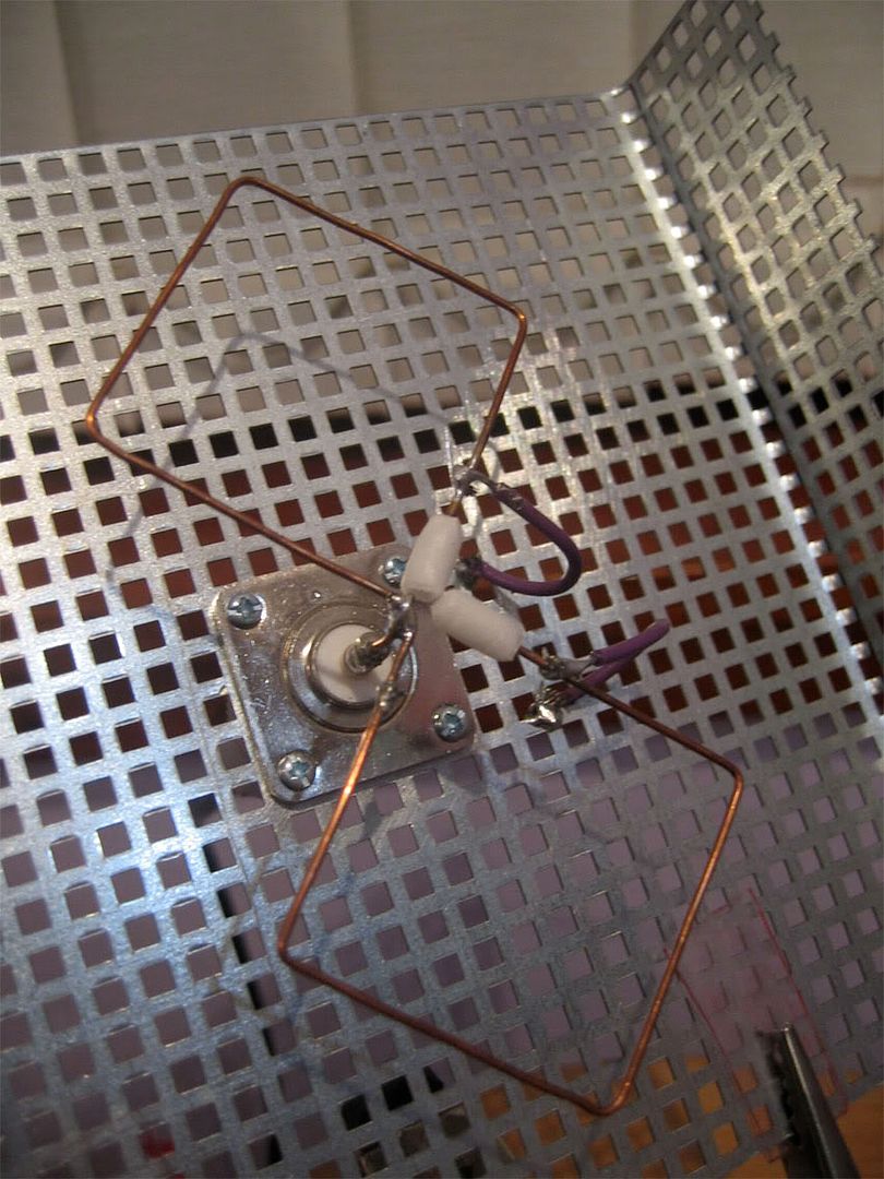
I made the reflector out of galvanised steel mesh and mounted an N-type connector to the centre. I made an N-type coaxial to FME coaxial cable to hook up the phone to the antenna. The emitter itself is made from the copper centre conductor taken from a length of high-quality satellite TV coaxial cable that I had left over. I used some scrap wires to connect the ends of the biquad ‘bow-tie’ back to the reflector, and placed some of the original dielectric insulation from the satellite cable back on the ends of the bow-tie’ shape to prevent the antenna from ’shorting’ (in an RF sense). The emitter is then soldered into the N-type connector in a most slapdash style.
I didn’t have enough mesh to make the ‘lips’ of the antenna’s reflector match the measurements I’d planned, but made them the longest equal lengths that I could. In other respects, I managed to get the dimensions down to within a couple of millimeters of my target measurements.
High-quality cable is a must - I only used 50cm or so of RG-58 type cable to go between the phone and antenna, and unless you’re using something very high-grade (like LMR-400), I wouldn’t go too much further than that.
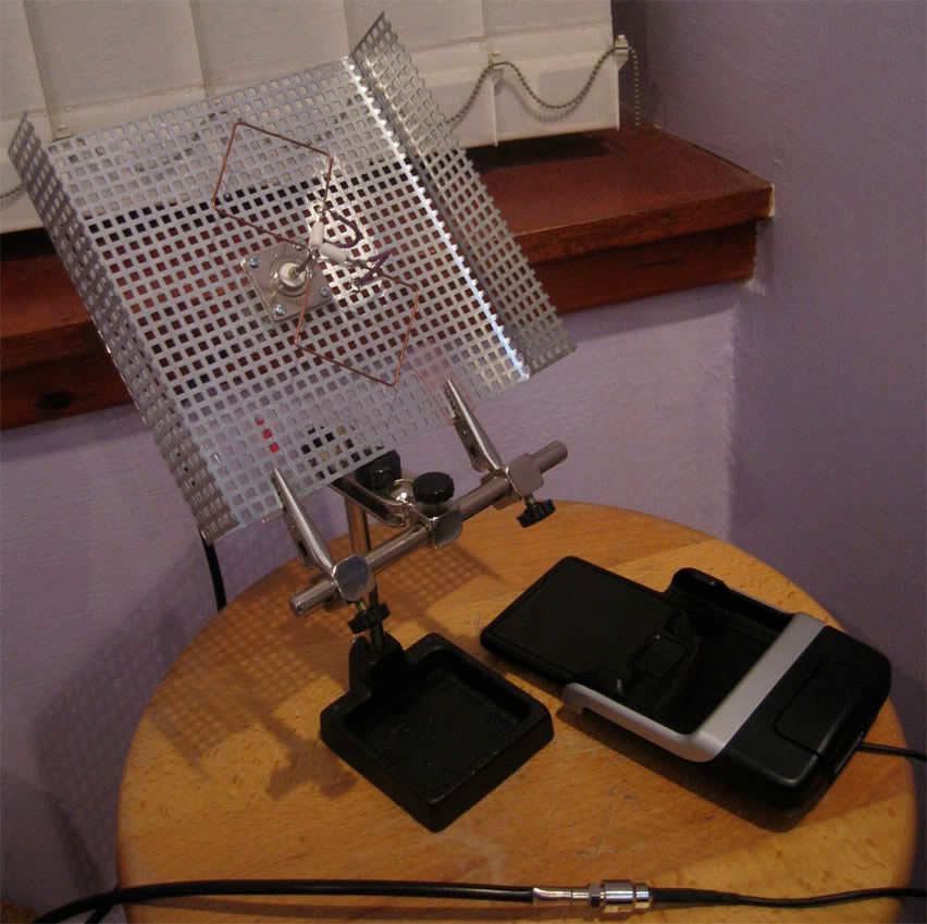
Presently the antenna is fixed and aimed in a pretty shoddy way - it’s fixed onto a set of ‘3rd hands’ - and there’s a Post-It note there to provide (some) insulation between the stand and the reflector… I plan to investigate more permanent mounting options at some other date.
The biggest problem with the antenna is aiming it - but having said that once it does catch a signal, the phone holds on to it very well. I’m aiming it over the rootfops of the building, hoping to catch some of the signal’s diffraction.
I have no idea how much gain the antenna produces. When aimed correctly (which is very tricky), it gives me a consistent 1-bar UMTS connection, or a 2 bar GSM signal. It works better at night, holding on to a signal for many hours.

UPDATE (3rd August 2006): Here are some better pics. I’ve replaced the post-it note with some pieces of polycarbonate. The pics also show the cradle into which the phone sits, and the cable which links the antenna to the phone.
Also, admire my lovely lavender wall paint :S
1 comment:
Hi, dropping in from 4 years after this was first posted (on the original blog) to add some new knowledge from 2010.
Nice antenna and good work on the calculations, but these days it seems all you need is a picture of Chuck Norris: http://www.intomobile.com/2010/09/26/chuck-norris-solves-iphone-4-signal-issues/
(intomobile[dot]com chuck-norris-solves-iphone-4-signal-issues)
Post a Comment